2026-09-16 ·
Pump Room Design for Data Center Cooling Systems
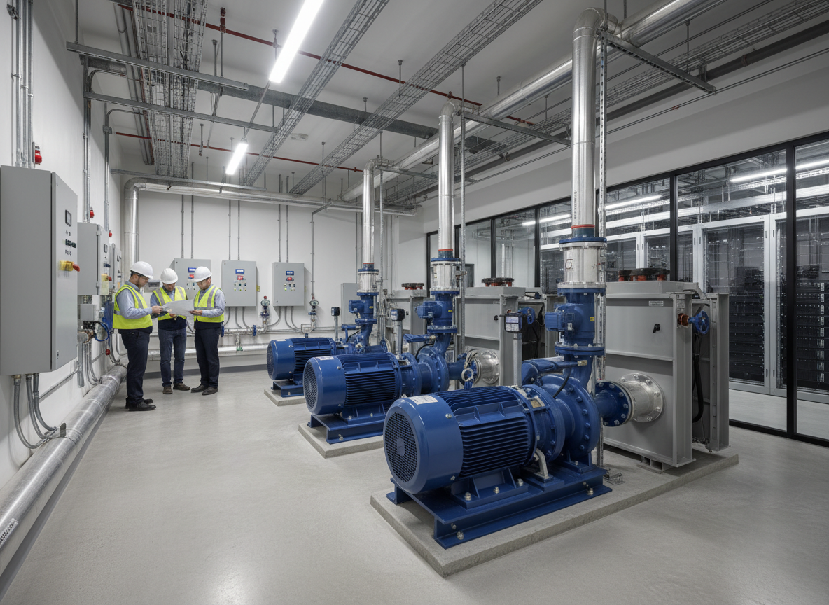
Effective pump room design is fundamental to the reliability and efficiency of any data center cooling system, directly impacting uptime and operational costs. A well-designed pump room ensures consistent coolant flow, maintains optimal temperature differentials, and provides the necessary pressure for heat rejection, which is critical for preventing thermal runaway in high-density IT environments. Key considerations include pump sizing based on flow rate and head pressure requirements, redundancy strategies to prevent single points of failure, and careful integration with the overall cooling architecture, whether air-side economization, chiller-based, or liquid-to-chip systems. The modular approach to these facilities, such as dedicated Pump and Equipment Rooms, can streamline deployment and enhance scalability.
Sizing and Selection of Pumping Equipment
The accurate sizing and selection of pumps are paramount, driven by the data center's total heat load and the chosen cooling technology. Engineers must calculate the required flow rate (typically in liters per second or gallons per minute) and the total dynamic head (TDH) to overcome friction losses in piping, valves, and heat exchangers, as well as static head differences. Oversized pumps lead to inefficient operation, increased energy consumption, and premature wear, while undersized pumps cannot deliver adequate cooling, jeopardizing IT equipment. Variable speed drives (VSDs) are almost universally employed to match pump output to the dynamic cooling demands, significantly improving energy efficiency, especially in facilities with fluctuating IT loads. Material selection for pump components, such as impellers and casings, must consider the coolant type and potential for corrosion.
Redundancy and Reliability Strategies
Data center pump rooms demand robust redundancy to ensure continuous operation even during equipment failure or maintenance. The most common redundancy schemes are N+1, 2N, or even 2N+1 for mission-critical facilities. N+1 redundancy involves having one extra pump beyond the minimum required for full load, allowing for a single component failure without impacting cooling capacity. 2N redundancy, often seen in hyperscale deployments, duplicates the entire pumping system, providing a completely independent backup. This level of redundancy extends beyond just the pumps to include associated piping, valves, and power feeds, ensuring no single point of failure can disrupt the cooling chain. Implementing automatic switchover mechanisms and comprehensive monitoring systems is crucial for these strategies to be effective.
Piping, Valves, and Ancillary Components
The design of piping networks, valve arrangements, and ancillary components within the pump room is critical for operational flexibility and maintenance. Proper pipe sizing minimizes pressure drop and ensures efficient flow, while material selection (e.g., steel, copper, or various plastics) depends on coolant type, pressure, and temperature. Isolation valves are essential for segmenting the system for maintenance without shutting down the entire cooling plant. Check valves prevent backflow, and balancing valves ensure even flow distribution across different cooling loops. Expansion tanks accommodate thermal expansion and contraction of the coolant, protecting the system from pressure surges. Strainers and filters are also vital for removing particulates that could damage pumps or foul heat exchangers, maintaining system cleanliness and efficiency. These components are often integrated into modular units, streamlining deployment.
Integration with Overall Cooling Architecture
A pump room does not operate in isolation; its design must be seamlessly integrated with the data center's broader cooling architecture. This includes connection to chillers, cooling towers, dry coolers, or direct liquid cooling distribution units. For facilities utilizing Liquid Cooling Considerations for Modular Deployments, the pump room might house primary and secondary loops for facility water and IT coolant, respectively. The control system integration is paramount, allowing the pump room to respond dynamically to changes in IT load and environmental conditions. This often involves a Building Management System (BMS) or Data Center Infrastructure Management (DCIM) platform that orchestrates the operation of all cooling components, from the pump room to the CRAC/CRAH units or direct-to-chip cold plates. Such integrated systems are often part of larger Modular Data Center Buildings or dedicated Cooling and Mechanical Modules.
Environmental and Safety Considerations
Beyond functional design, pump rooms must adhere to stringent environmental and safety standards. This includes proper ventilation to manage heat generated by pumps and motors, as well as to mitigate potential leaks or spills. Secondary containment measures, such as sumps and floor drains, are crucial for preventing coolant from impacting adjacent areas or the environment. Noise attenuation should be considered, especially if the pump room is near occupied spaces. Fire suppression systems, appropriate for the specific coolants used, are also a non-negotiable safety feature. Access for maintenance personnel, clear labeling of pipes and valves, and emergency shut-off procedures are all part of a comprehensive safety design that protects both equipment and personnel, ensuring long-term operational integrity.